ESP32 water level sensor
August 11, 2024
ESP32 Water Level Sensor
In this article, I’ll show you how I created a water level sensor that sends notifications via Telegram and email using an ESP32 and a few simple components. This project allowed me to solve a problem I had while also learning more about hardware development.
Reason
The main reason I developed this device is that I had no way of knowing when my air conditioner’s water tank was full and needed to be emptied. With this sensor, I receive alerts when the tank is about to overflow. It's important to note that this is one of my first hardware projects, so there might be aspects that are not 100% accurate. Nevertheless, I hope this article is helpful if you're considering a similar project.
Components Used
ESP32
The ESP32 is the main component of this project. It's a highly versatile development board that, in addition to having all the functionalities of a board like the Arduino Uno, offers wireless connectivity via Wi-Fi and Bluetooth.
Water Level Sensor
There are several types of sensors for measuring water level, but I opted for a float sensor because it fits my needs very well. This type of sensor is more suitable for my case than other alternatives, such as ultrasonic level sensors.
Other Components
- A switch to turn the device on and off.
- A battery holder to power the ESP32.
- A waterproof circuit box to protect the components.
System Design
Backend
The system is designed to store sensor readings in a database and send notifications when the water level reaches a critical point. To achieve this, I developed a custom backend using Fastify. This backend is configured to log the sensor readings and send a notification to Telegram, via email, or both when a specific endpoint is called. If you're interested in replicating this project, you can find my backend code https://github.com/pavece/esp32-watersensor.
ESP32
To interact with the API, I created a script for the ESP32 that takes advantage of the device's sleep modes. The ESP32 remains in Deep Sleep mode, meaning it consumes very little power while waiting for the sensor to activate. When the sensor detects that the water level has reached the set point, it sends a HIGH signal to a GPIO pin on the ESP32, waking it up and triggering the request to the backend. Once the notification has been sent, the ESP32 goes back into Deep Sleep until the device is turned off and on again using the switch. This behavior ensures that the system doesn't send multiple notifications for a single event, which could happen due to the specific characteristics of this float sensor. Here is the script used by the ESP32, so you can use it if you decide to replicate this project.
1#include <HTTPClient.h>
2#include <WiFi.h>
3#include <Arduino_JSON.h>
4
5const char* ssid = "";
6const char* password = "";
7
8const String sensorAPIUrl = "";
9
10RTC_DATA_ATTR int bootCount = 0;
11
12void blinkLed(int times, int ledPin){
13 pinMode(ledPin, OUTPUT);
14 for(int i=0; i<times; i++){
15 digitalWrite(ledPin, HIGH);
16 delay(100);
17 digitalWrite(ledPin, LOW);
18 delay(100);
19 }
20}
21
22void saveLog(){
23 WiFi.begin(ssid, password);
24
25 while(WiFi.status() != WL_CONNECTED){
26 delay(500);
27 }
28
29 if(WiFi.status() == WL_CONNECTED){
30 HTTPClient http;
31
32 //Register the reading
33 http.begin(sensorAPIUrl);
34 int result = http.POST("");
35
36 if(result != 200){
37 blinkLed(5, 2);
38 return;
39 }
40
41 blinkLed(2, 2);
42 }
43
44 esp_deep_sleep_start();
45}
46
47void setup() {
48 // Executed when powered up
49 if(bootCount == 0){
50 bootCount++;
51 esp_sleep_enable_ext0_wakeup(GPIO_NUM_4, 1);
52 esp_deep_sleep_start();
53 }
54
55 //Only executed once
56 saveLog();
57}
58
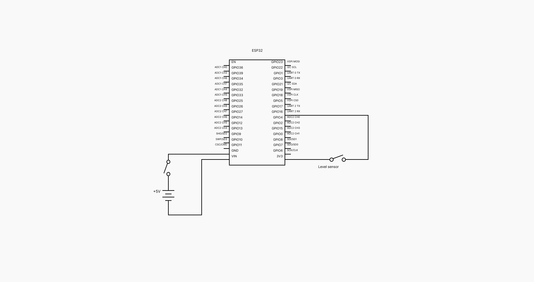
59void loop(){}Connections
Here is a simple schematic showing how I connected all the components. The Switch is connected to the battery and functions as an on/off switch. The sensor is connected to the ESP’s 3.3V output and GPIO 4. When the water reaches the level, the sensor closes the circuit and the ESP wakes up.
Results and Next Steps
In this case I also created a Grafana dashboard to view every sensor reading.
I’m aware that tools like ESPHome and Home Assistant exist, which could have made this project easier and faster to implement. However, I chose to create a fully custom solution to deepen my understanding of hardware and software integration and to learn more through the process.
There are many possibilities for expanding this project, such as:
- Integrating more advanced sensors to measure the volume of water and generate usage graphs.
- Adding more notification methods, like SMS.
- Optimizing the system's energy consumption.
- Integrating with Home Assistant.
Here is a photo of the result:
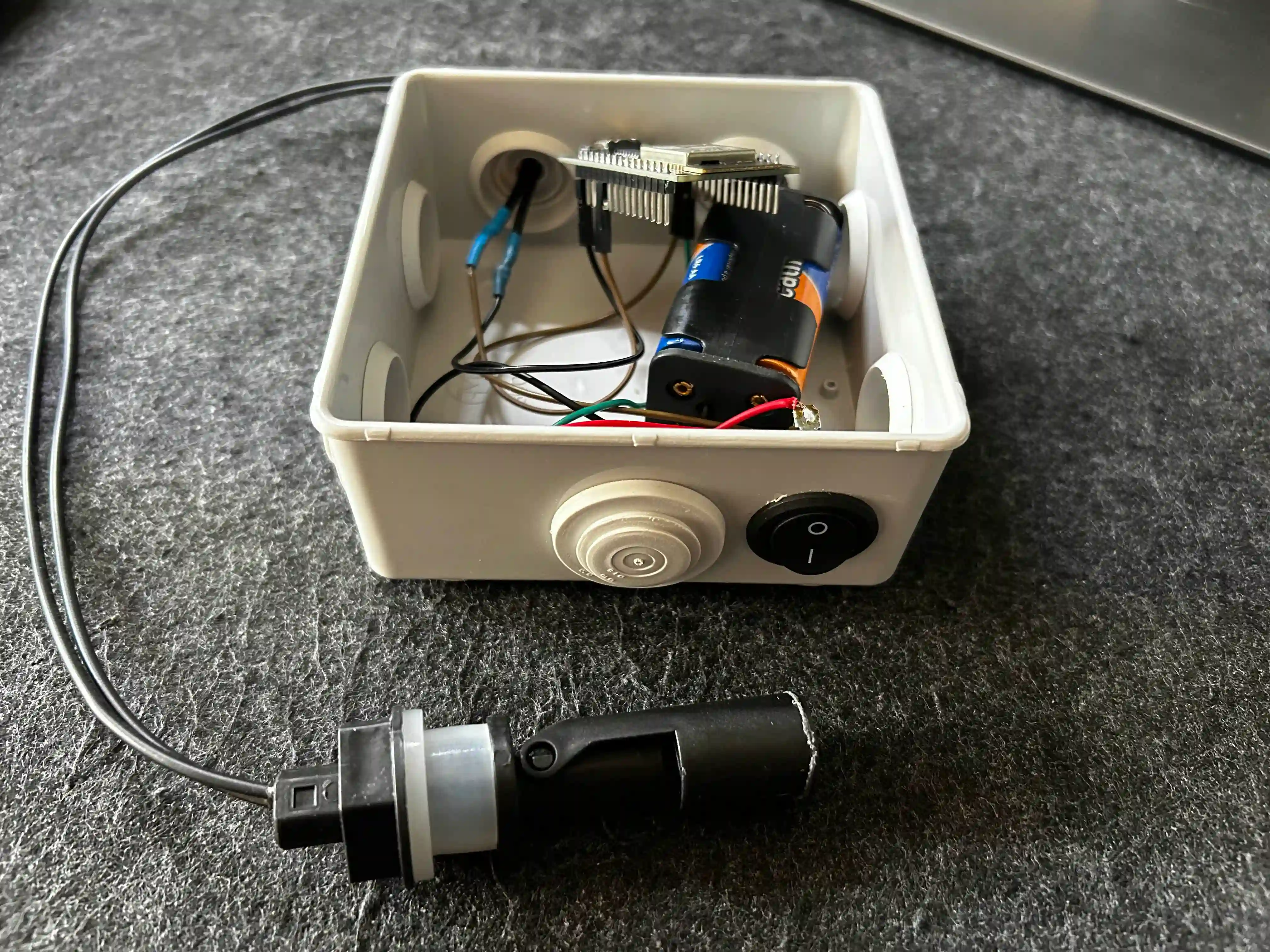
Hope you liked this article !